
Fiber Splicing and Forming: Ring-shaped CO2 laser beams advance optical fiber processing
source:Laser Focus World
release:Nick
keywords: CO2 laser lasers optical fiber
Time:2018-01-20
For decades, optical fiber processing relied on conventional heating methods such as filaments or electrodes. While laser heating was a known alternative since the 1970s, the availability of affordable carbon-dioxide (CO2) laser sources has recently sparked commercial interest in this technique.1
Processing with a CO2 laser provides a number of clear advantages. The laser source is inherently clean, meaning it will not lead to any contamination in the final component such as is possible with chemical-based electrodes. The laser also remains extremely stable for a long period of time, reducing maintenance requirements.
However, the main benefit is that heating through absorption is inherently different compared to other electrical surface-heating techniques. By using absorption, the heating process can be directed to exactly the places that are crucial for the process. Directed heating not only increases the quality of available fiber-optic components, but allows fabrication of unique fiber shapes and designs.
For absorption-based heating to be effective, beam-shaping tools are crucial. With this in mind, Nyfors (Stockholm, Sweden) and Fraunhofer Institute for Applied Optics and Precision Engineering (Fraunhofer IOF; Jena, Germany) collaborated on developing a product called Smartsplicer and settled on a ring-shaped beam that allows an optical fiber to be addressed from approach angles over a full 360°.
The ring is formed by patented Axicon Splicing technology and a motorized telescope in front allows the ring size and thickness to be varied, increasing process flexibility. In addition, the dynamic optical system includes the ability to change the incidence angle of the laser beam for optimal heating. The laser beam can be focused into an annular shape for end-cap splicing, for example, or focused on the lateral sides of a fiber for fiber-to-fiber splicing, tapering, or for manufacturing fiber combiners (see Fig. 1).

FIGURE 1. A schematic shows different configurations for the laser beam (red) for end-cap splicing (a) and for both tapering and fiber-to-fiber splicing (b). (Courtesy of Nyfors)
The advantages of Smartsplicer are best illustrated by a variety of special applications. Nyfors has partnered with the Swedish Research Institute (RISE; Stockholm, Sweden), Serstech (Lund, Sweden), and the Swedish police to develop a new fiber sensor. In the project, funded by the Swedish government agency VINNOVA, the collaborators aim to construct a fiber sensor that can be used to detect trace gases at crime or accident scenes.
Currently, police dogs are the most effective way to detect gases. However, these dogs cannot communicate the gas that is present and are not always available. A police officer arriving at a scene should be able to quickly identify whether there are volatile gases in the air. By using a hollow-core fiber that can be filled quickly with the surrounding gas and sending a light through it, a Raman spectrum of the gas can be obtained since the light is able to interact over a long length of fiber for proper amplification. To make this possible, however, it is critical to splice a hollow-core fiber to an ordinary fiber.

FIGURE 2. A typical, fragile hollow-core fiber for sensing applications. (Courtesy of RISE)
For accurate sensing, the splice must be accomplished without collapsing the fragile inner structure of the hollow-core fiber, while still achieving high splice strength (see Fig. 2). During heating, the inner structure of a hollow-core fiber typically collapses—therefore, the heating needs to be well controlled and must only affect the outer layer of the fiber. At the same time, the splice must be mechanically strong as these sensors are meant for field use. The best way to achieve this is to ensure that fiber is fused with equal strength all the way around its circumference, making a laser ring extremely beneficial for this task.

FIGURE 3. A photonic crystal fiber (PCF) is shown in stages as it is spliced to an end cap; where the fiber looks solid (far right), the structure has collapsed. (Courtesy of Fraunhofer IOF)
Fraunhofer IOF has used Smartsplicer to demonstrate splicing of a photonic-crystal fiber (PCF) to standard fiber.2 While the inner structure is different in PCFs than in hollow-core fibers, the basic challenge remains the same: use controlled laser heating to make sure collapse of the fiber structure is controlled (see Fig. 3). During the splicing process, a larger part of the fiber is collapsed close to the splice point. As the splicing process progresses, the edges of the fiber are fused to the endcap and the internal structure of the fiber is intact even at the splice interface (see Fig. 4).

FIGURE 4. The completed splice interface is shown between an end cap and a photonic crystal fiber. (Courtesy of Fraunhofer IOF)
The mechanical stability of this splice remains high because of the ability to create a fuse all the way around the fiber. These experiments show that the ring-shaped laser beam provides optimal control over all processes, which is required to manufacture such delicate components.
The process of endcapping is important if large amounts of power are to be passed through a fiber. When the light exits the fiber into air, the air-fiber interface will scatter the light. If this scatter is concentrated on the small diameter of a fiber, the concentration of power can easily damage it. Therefore, by adding an end cap the light can be dispersed over a larger area before it enters into the air.
Of course this only works if the fiber is spliced to the endcap such that no light is scattered at this interface. It is therefore extremely important that the splice is completely contamination-free and the fiber is uniformly attached. For high laser powers this is only achievable to date with CO2 laser splicing technology.
Because of the setup of the ring-shaped laser beam with controlled incidence angle, the size of the lower splice surface is practically unlimited. The size or even the shape of an end cap therefore becomes almost irrelevant for the splice process. As lasers increase in power it will become ever more important to splice larger end caps.
Because the ring size and thickness are also easily varied, very small and very large fibers can be processed. The ring can be changed so that only the area to which the fiber will attach to is heated precisely and uniformly. This leads the rest of the endcap undisturbed and means potential antireflection (AR) coatings or other features will not be damaged.
Fiberguide Industries (Caldwell, ID) has been using Smartsplicer technology to successfully splice fibers and end caps of varying sizes, such as a 400-μm-diameter fiber spliced to a 10-mm-diameter end cap (see Fig. 5). Because of the nature of the beam setup, splices to surfaces of several centimeters in diameter have been achieved. Fiberguide has also produced 800-μm-diameter ball lenses on a 600 μm fiber, achieving 10 μm accuracy on the final diameter with a straightness accuracy of 25 μm—a significant improvement compared to conventional techniques.

FIGURE 5. A 400-μm-diameter fiber is spliced to a 10 mm diameter end cap (a), and an 800-μm-diameter ball lens is fabricated on the end of a 600-μm-diameter fiber (b). (Courtesy of Nyfors and Fiberguide Industries, respectively)
Other laser beam configurations are used for tapering processes—the reduction of the diameter of a fiber over a certain length. Tapering is important for numerous applications. Frequently, it is desired to match different fiber sizes for a splicing process. Tapers can also be used to filter out certain undesired optical fiber transmission modes.
Most applications for tapering have a few things in common, however. First, it is important that the specific target diameter is reached precisely and that wanted light is not lost because of irregularities. Second, to achieve a precise target diameter it is important to use precise and stabilized axial movement to precisely control the speed of the fiber as it is pulled through the laser heating zone. And finally, to prevent the loss of light, the fiber must be tapered adiabatically.
By using a ring-shaped beam, light illuminates 360° of the fiber circumference. The angle of incidence is set so that the light is absorbed efficiently and the telescope can be used to control the size of the heating zone. Such uniform heating is extremely important when processing very large fibers up to 3 mm, but also when handling fragile components.
In fiber lasers, it is common to combine light from several pump lasers as well as a seed laser in a fiber combiner. To accomplish this, all fibers are collected in a capillary and the arrangement is tapered down to match the single fiber that is subsequently spliced to the combiner. To achieve high-quality products, it is necessary that the component is heated uniformly—that is, if some fibers in the capillary receive less or uneven heating, the combiner will be asymmetric.

FIGURE 6. The Smartsplicer performs CO2-laser-based glass processing and splicing. (Courtesy of Nyfors)
As laser splicing systems are becoming more affordable and commercially available, the possibilities for fiber processing are increasing dramatically (see Fig. 6). Not only does technology like the Smartsplicer improve the quality of fiber-optic components, it also enables fabrication of contamination-free components that were not possible before.
1 H. Fujita, Y. Suzaki, and A. Tachibana, Appl. Opt., 15, 2, 320–321 (1976).
2. S. Böhme et al., "End cap splicing of photonic crystal fibers with outstanding quality for high-power applications," Proc. SPIE, 8244, 824406 (2012).
 FISBA exhibits Customized Solutions for Minimally Invasive Medical Endoscopic Devices at COMPAMED in
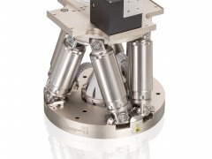 New Active Alignment System for the Coupling of Photonic Structures to Fiber Arrays
 A new industrial compression module by Amplitude
 Menhir Photonics Introduces the MENHIR-1550 The Industry's First Turnkey Femtosecond Laser of
 Shenzhen DNE Laser introduced new generation D-FAST cutting machine (12000 W)